Computer Organization & Architecture
Understanding the internal workings of computer systems
About The Subject
Explore the fundamentals of computer hardware and architecture
Overview
Computer Organization and Architecture (COA) is the study of the internal structure, design, and functioning of a computer system. It focuses on how hardware components interact to execute software instructions efficiently. COA bridges the gap between hardware and software, helping students understand how computers actually work.
CPU Architecture
The brain of the computer responsible for executing instructions. It consists of the Arithmetic Logic Unit (ALU), Control Unit (CU), and Registers.
Memory Organization
Explains how data is stored and accessed. Includes concepts like primary memory (RAM, ROM) and secondary storage, as well as cache memory.
Instruction Set Architecture
Defines the set of instructions a processor can execute, including data types, addressing modes, and control operations.
I/O Organization
Describes how a computer communicates with external devices using I/O interfaces, buses, and data transfer techniques like DMA.
Pipelining
Techniques used to increase CPU performance by overlapping instruction execution and utilizing multiple processors.
Control Unit Design
Explains how control signals are generated to coordinate all hardware operations, using hardwired or microprogrammed control.
Faculty Information
Meet your course instructor
Ms. RADHIKA
Assistant Professor
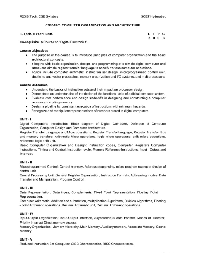
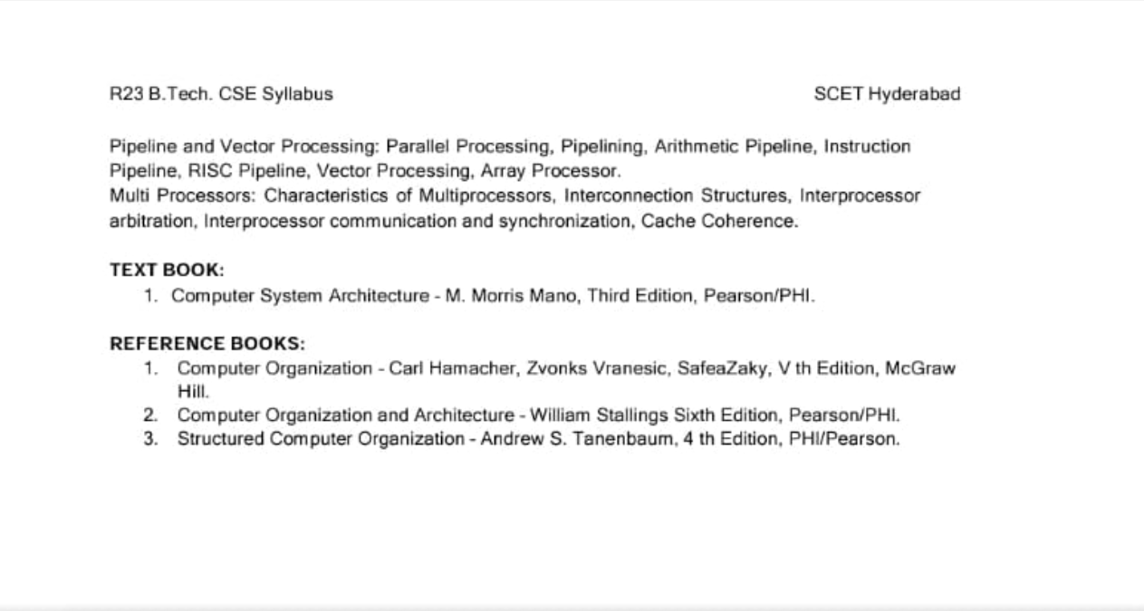
Syllabus
Complete course curriculum and topics
Study Materials
Download notes and reference materials
Click to download the complete COA notes (PDF, ~3.2MB)
Important Questions & Answers
Previous year questions with detailed solutions
Answer:
A digital computer is an electronic system that processes information using binary digits (0 & 1). It accepts data, performs operations according to instructions, stores intermediate results, and generates output.
KEY CHARACTERISTICS:
- Works on binary system (0 & 1)
- High speed & accuracy
- Programmable & versatile
- Large storage capacity
- Automation and reliability
APPLICATIONS:
- Scientific research (simulations, weather forecasting)
- Business applications (payroll, banking, accounts)
- Engineering (CAD tools, circuit design)
- Medical (diagnosis, imaging)
- Education & communication (online learning, networking)
SUMMARY:
Digital computers are fast, accurate and versatile machines used across science, business, engineering and daily life.
Answer:
A bus system provides a common pathway for data transfer among components in a system with four registers (R1-R4).
-
MULTIPLEXER:
Selects which register sends data to the bus
-
DECODER:
Activates the correct destination register to receive data
-
CONTROL LINES:
Manage read/write operations
SUMMARY:
A bus system reduces hardware complexity while allowing multiple registers to share a single data path.
Answer:
a) CONTROL UNIT DESIGN:
The Control Unit (CU) directs operations in the CPU by generating control signals. Inputs include the instruction register, flags, and clock. Outputs are signals to ALU, memory, and input/output devices.
b) COMPARISON:
-
HARDWIRED CU:
Implemented with combinational logic, very fast but inflexible, used in RISC processors
-
MICROPROGRAMMED CU:
Uses microinstructions stored in control memory, slower but flexible, easy to modify, used in CISC processors
SUMMARY:
Hardwired CU = fast but rigid; Microprogrammed CU = flexible but slower
Answer:
Addressing modes define how operands are accessed in instructions.
-
IMMEDIATE: Operand in instruction
Example: MOV A, #5
-
DIRECT: Address of operand given in instruction
Example: MOV A, 1000
-
INDIRECT: Instruction points to memory location containing operand's address
Example: MOV A, (R1)
-
REGISTER: Operand in register
Example: ADD A, R1
-
INDEXED: Effective address = base + index register
Example: MOV A, 1000(R2)
-
RELATIVE: Address relative to PC
Example: JMP 20
SUMMARY:
Addressing modes provide flexible ways to access operands during instruction execution.
Answer:
Floating point representation is used to store real numbers (fractions, very large, or small values).
- GENERAL FORM: N = (-1)³ × M × 2⁶
-
IEEE 754 SINGLE PRECISION (32-BITS):
- 1 bit: Sign (S)
- 8 bits: Exponent (E), bias = 127
- 23 bits: Mantissa (M)
- EXAMPLE: 5.75 → Sign = 1, exponent in biased form, mantissa is binary fraction
SUMMARY:
Floating point allows storage of very large/small real numbers efficiently.
Answer:
a) COMPUTER ORGANIZATION:
Internal hardware implementation details (ALU, memory, control signals), not visible to programmers.
COMPUTER ARCHITECTURE:
Programmer's view (Instruction set, addressing modes, data types) visible to programmers.
b) INSTRUCTION FORMAT:
Defines binary layout of instruction with fields like opcode, mode, register, and address.
c) DATA TYPES:
- Integer
- Floating point
- Character
- String
SUMMARY:
Organization = hardware details. Architecture = programmer's view. Instruction format structures instruction. Data types define kinds of values.