Digital Electronics
Master the world of digital circuits and logic design
About The Subject
Explore the fundamentals of digital logic and circuit design
Overview
Digital Electronics is the branch of electronics that deals with digital signals and the design of circuits that use logic gates to perform various operations. Unlike analog electronics, which use continuous signals, digital systems represent data using discrete values — typically binary digits (0 and 1). This makes digital systems more reliable, scalable, and easy to design.
Number Systems
Digital electronics uses binary, octal, decimal, and hexadecimal number systems to represent and manipulate data efficiently in different contexts.
Logic Gates
Basic building blocks of digital circuits that perform logical operations like AND, OR, NOT, NAND, NOR, XOR, and XNOR gates.
Boolean Algebra
A mathematical method used to simplify and analyze logic circuits using algebraic expressions and theorems like De Morgan's laws.
Combinational Circuits
Circuits whose output depends only on the current inputs, such as adders, multiplexers, decoders, and encoders.
Sequential Circuits
Circuits whose output depends on both current inputs and previous states. Examples include flip-flops, counters, and shift registers.
Karnaugh Maps
A graphical method used to simplify Boolean expressions and minimize logic circuits for optimal performance.
Faculty Information
Meet your course instructor
Mr. RAVI
Assistant Professor
Syllabus
Complete course curriculum and topics
Study Materials
Download notes and reference materials
Click to download the complete Digital Electronics notes (PDF, ~3.8MB)
Important Questions & Answers
Previous year questions with detailed solutions
Answer:
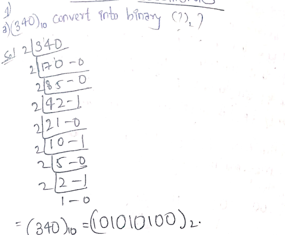
a) Convert (340)₁₀ into binary (?)₂:
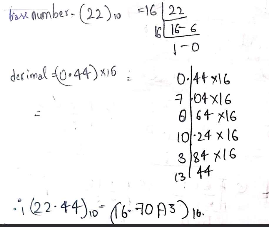
b) Convert (22.44)₁₀ into hexadecimal number (?)₁₆:
c) Explain De Morgan's theorem:
De Morgan's theorems are two fundamental rules in Boolean algebra that relate AND, OR and NOT operations. They state that:
- The complement of conjunction (A·B) is the disjunction of complements (A̅ + B̅)
- The complement of disjunction (A+B) is the conjunction of complements (A̅ · B̅)
Answer:
Answer:
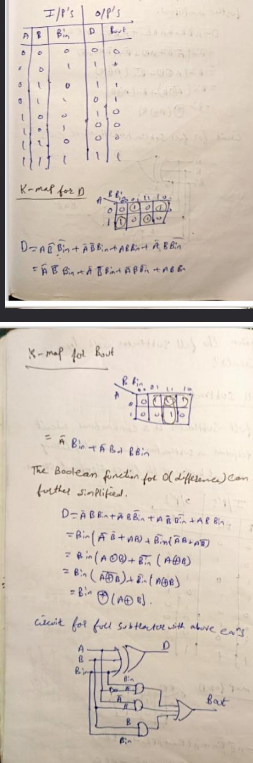
FULL SUBTRACTOR:
A full subtractor is a combinational circuit that performs subtraction between two bits, taking into account borrow from the lower significant stages.
Answer:
a) Convert (1010110110)₂ into gray code:
(1010110110)₂
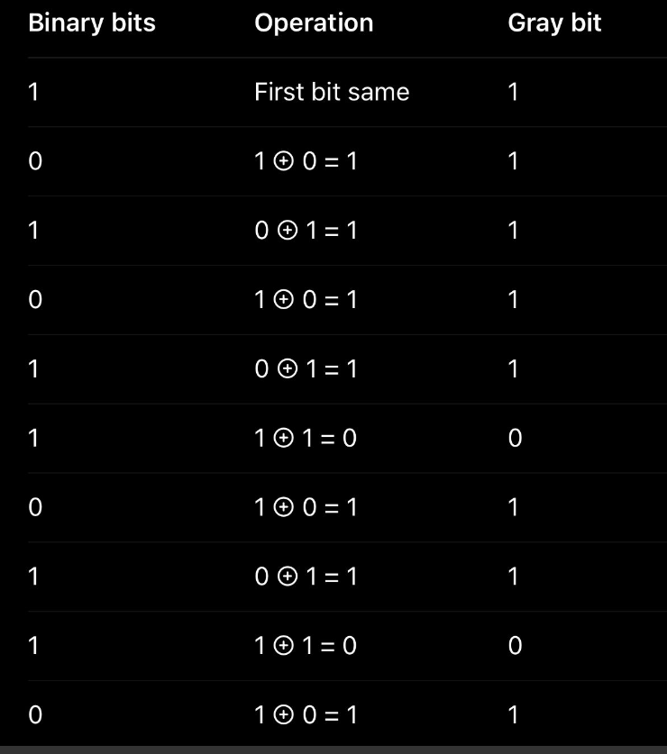
Final gray code is (1111101101)₂
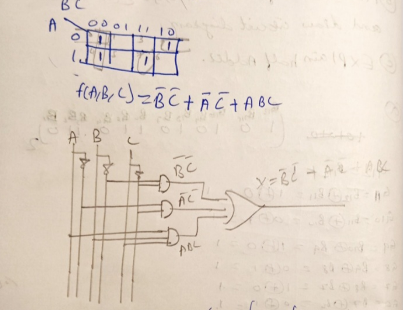
b) Minimize the function F(A, B, C) = Σm(0, 2, 4, 7) and draw circuit diagram:
F(A, B, C) = Σm(0, 2, 4, 7)
c) Explain half adder:
The logic circuit which performs the addition of 2 binary numbers is called a half adder.